


Workshop Ventilation System: What to Know?
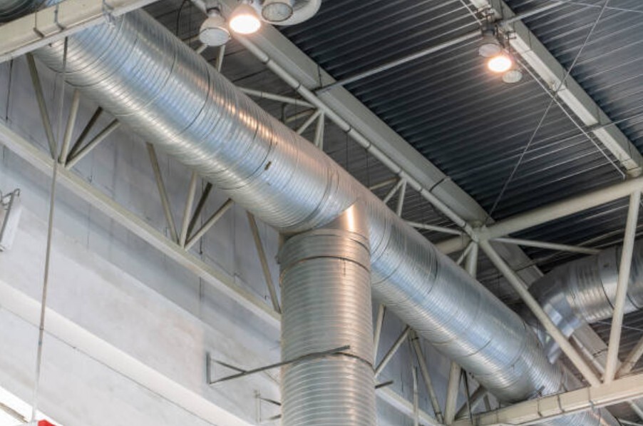
Air in a workshop never sits still. Grinding, welding, and cutting release particles that circulate through every corner of the space. A well-designed workshop ventilation system moves contaminated air through controlled paths so every tool and operator stays within safe limits.
Contaminants, Heat, and Pressure — The Forces Driving Workshop Ventilation
Air inside enclosed work areas fills quickly with particulates, vapors, and excess heat from tools, machinery, and processes such as welding or painting.
Common contaminants include:
- Metallic fumes from welding and cutting
- Fine dust from sanding, wood, or composite work
- Vapors from paints, adhesives, or solvents
- Moisture from cleaning or curing
Because each contaminant behaves differently—rising, settling, or dispersing—a workshop ventilation system must capture pollutants at their source before they accumulate.
- An effective ventilation strategy:
- Dilutes airborne contaminants
- Exhausts high-temperature air
- Prevents negative pressure that can draw dust or fumes from adjacent rooms
Once the main airflow paths are understood, the next consideration is how codes define minimum exchange and contaminant limits. ASHRAE 62.1, OSHA 1910, and IMC §502.14 specify those requirements for most shops, ensuring airflow remains within safe, code-recognized limits. Meeting those standards also keeps energy use in check — and that matters when fans run all day.
Types of Workshop Ventilation Systems
Each system handles air differently depending on the process and layout. Choosing the right configuration depends on what is being produced, how often doors open, and where pollutants originate.
Supply Systems
A supply system introduces clean air from outdoors or filtered intake ducts to pressurize the workspace slightly above surrounding rooms. Positive pressure helps prevent outdoor dust or exhaust from entering. Designers size fans to deliver steady air changes per hour (ACH) while maintaining stable indoor temperatures.
Exhaust Systems
Exhaust-dominant systems remove air through ducts, hoods, or roof vents located near contaminant sources. These systems are common in welding, sanding, and finishing areas where removing fumes takes priority over temperature balance. Negative pressure can pull unfiltered air inward through cracks, so exhaust systems include controlled make-up-air inlets or adjustable dampers to stabilize pressure — something every shop manager has seen when a door slams shut from suction.
Balanced Systems
A balanced workshop ventilation system combines both methods — equal parts supply and exhaust — using controls to maintain neutral pressure. This approach stops contaminants from spreading between zones and stabilizes energy use in conditioned spaces. Balanced configurations are typically required for facilities handling variable contaminant loads or temperature-sensitive materials.
Effective design also divides the shop into pressure zones. Welding bays and paint areas use dedicated exhaust paths, while general spaces rely on dilution air. Locating exhaust points near the floor for heavy particulates and near the ceiling for heat and fumes maintains uniform air turnover throughout the workshop.
When Natural Ventilation Might Be Enough
Natural ventilation relies on cross-breezes, roof vents, or operable louvers to exchange indoor and outdoor air without mechanical fans. It can work in large, low-emission spaces or detached garages where contaminant levels remain minimal.
However, airflow depends entirely on wind and temperature differences. It cannot guarantee consistent capture of fumes or meet code requirements in most industrial environments. For workshops with heat, dust, or chemical vapors, a mechanical workshop ventilation system using controlled supply and exhaust remains the reliable choice.
Key Design Factors for Workshop Ventilation
Proper design goes beyond simply choosing fans. Each workshop’s size, occupancy, and process dictate airflow rate, air distribution, and filtration.
Airflow Rate and ACH
To confirm your system meets safety standards, you’ll need to calculate exactly how many air changes occur each hour.
How do you calculate air changes per hour in a workshop?
Light manufacturing typically requires 4–6 ACH, while welding or solvent operations may exceed 12. Calculations should include exhaust-hood capture efficiency and system resistance to maintain target cfm at all outlets. Airflow calculations follow principles outlined in Understanding Industrial Ventilation Systems and Factory Ventilation.
Sizing Your Ventilation System: Formulas and Calculations
Ventilation sizing begins with the relationship between room volume and desired air-change rate:
CFM = (Volume × ACH) ÷ 60.
Room volume equals length × width × height, measured in cubic feet. Dividing by 60 converts the hourly air-change requirement into cubic feet per minute.
- For example, a light-fabrication workshop using 6 ACH moves roughly one room-volume of air every ten minutes.
- Welding or finishing areas often require 10–12 ACH to control fumes and heat.
Designers adjust that base figure for duct losses, hood capture efficiency, and the number of occupied workstations. Reference data from ASHRAE 62.1 Tables 5-1 and 6-1 help confirm minimum rates for process areas and general ventilation zones.
Contaminant Control
Identify sources — particulate, vapor, or heat — and position exhaust points accordingly. Local exhaust at workstations often pairs with general dilution ventilation for background contaminants. Capture velocity, duct sizing, and filter media selection determine how effectively particles or fumes are removed.
Temperature and Humidity
Workshops with heat-producing equipment may require tempered make-up air or energy-recovery ventilators to balance comfort and efficiency. In humid climates, condensate control prevents corrosion on machinery and maintains consistent airflow through louvers.
Incoming air often passes through filtration and conditioning units to protect both occupants and equipment. High-efficiency filters capture fine dust, while activated-carbon stages absorb odors and vapors. In cold climates, make-up-air heaters prevent condensation on metal surfaces; in warm, humid regions, dehumidification keeps air density and cooling load stable.
Safety and Maintenance
After maintenance comes measurement—understanding your system’s airflow rate helps verify that your ventilation is doing its job.
How often should workshop ventilation systems be inspected?
Mechanical ventilation must align with OSHA and NFPA 91 standards when combustible dusts or vapors are present. Regular inspection of belts, filters, and dampers keeps pressure steady, cuts noise, and prevents those mid-shift surprises no one wants.
Quarterly filter cleaning and damper calibration help maintain steady pressure and reduce energy costs. Documenting these tasks preserves code compliance and reduces lifecycle energy expense.
Monitoring and Control Systems
Modern ventilation relies on automatic feedback. Differential-pressure sensors, occupancy detectors, and variable-frequency drives (VFDs) modulate fan speed to maintain target airflow without wasting energy. Control dampers respond to real-time readings, balancing supply and exhaust when doors open or equipment loads change.
Advanced systems also integrate airflow alarms and CO₂ sensors in occupied zones to verify that ventilation matches load conditions. These automated controls document performance for inspectors and reduce long-term energy consumption compared with constant-speed operation.
Louvers and Dampers in System Performance
Louvers and dampers regulate how air enters, exits, and balances within the system. They function as both mechanical and protective components.
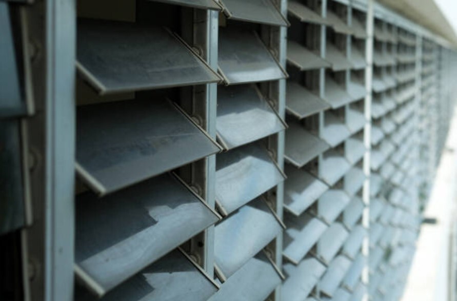
Louvers
Exterior louvers shield intake and exhaust openings from rain, debris, and back-draft while preserving free area for airflow. United Enertech manufactures models tested under AMCA 500-L for air-performance and water-penetration ratings. Specifiers choose blade depth and spacing according to airflow needs and design pressure.
Typical free-area ratios range from 45 to 55 percent, influencing fan sizing and pressure drop. Selecting models with published sound-power data helps maintain acceptable decibel levels near work areas.
Dampers
Control and back-draft dampers adjust air volume and direction inside ducts. Fire and smoke dampers are UL 555-tested to close automatically when temperature thresholds are reached, isolating affected zones. Leakage performance follows UL 555S Class I or II ratings, critical for maintaining pressure integrity between zones.
Balancing dampers fine-tune system pressure to maintain design airflow across multiple workstations. Together, these components help engineers fine-tune how a workshop ventilation system performs under varying loads and conditions.
Performance Verification in Workshop Ventilation
After installation, airflow readings confirm that each workshop ventilation system performs as designed. Technicians measure velocity pressure at diffusers or duct sections using pitot tubes or anemometers, converting results to cubic feet per minute (cfm). A variation of ±10 percent from design flow is typically acceptable.
Supply and exhaust zones should remain within ±0.02 in. w.g. of target pressure to avoid drafts or backflow. Documenting these results forms part of the mechanical system’s commissioning record for building inspectors.
Compliance and Testing Requirements
Ventilation performance comes down to numbers and test data — never guesswork.
- ASHRAE 62.1 defines minimum outdoor-air rates and system design for acceptable indoor-air quality.
- OSHA 1910.94 governs ventilation for dusts, fumes, and mists, requiring hoods or ductwork sized to maintain capture velocity.
- NFPA 91 specifies construction for exhaust systems conveying combustible fumes, ensuring ducts and fans are non-sparking and properly grounded.
- Component verification relies on AMCA 500-L test data for louvers and UL 555 listings for fire/smoke dampers.
Documenting compliance with these standards confirms that airflow, noise, and safety targets are met before occupancy or inspection. Every standard and component works toward the same end — stable, code-ready air movement.
Achieve Code-Compliant Workshop Ventilation with United Enertech
United Enertech designs and manufactures louvers, dampers, and control assemblies engineered for precise airflow management in industrial environments. Each component is field-tested for pressure, durability, and full code compliance. Contact us today for specification support or project consultation.